Learn how to select a patient monitoring cable assembly for reliable medical signal connections. This guide covers ECG and SpO2 connector configurations, pin assignments, signal integrity, patient-contact materials, cleaning compatibility, and quality verification requirements.
A patient monitoring cable assembly connects sensors, electrodes, and monitoring accessories to medical equipment. Its configuration depends on the physiological signal, monitor interface, patient connection, and intended operating environment. Connector compatibility alone is not enough; pin assignments, electrical characteristics, and device-specific requirements must also match.
For medical equipment manufacturers, the main selection challenge is ensuring reliable signal transmission while maintaining practical handling, cleaning compatibility, and mechanical durability. ECG, SpO2, and temperature monitoring connections may look similar externally but have different electrical and configuration requirements.
What Determines a Patient Monitoring Cable Assembly Configuration?
Start with the monitor model, accessory type, and signal pathway. Each monitoring function has its own connection requirements and wiring arrangements.
Common applications include:
| Monitoring application |
Cable configuration considerations |
Main design priority |
| ECG monitoring |
Trunk cables, multi-lead branches, electrode connections |
Correct lead mapping and signal transmission |
| SpO2 monitoring |
Sensor connection and monitor-side interface |
Connector compatibility and signal stability |
| Temperature monitoring |
Probe connections and specified conductor arrangements |
Accurate electrical connection |
| Multi-parameter monitoring |
Multiple interfaces and accessory connections |
Correct identification and circuit separation |
ECG cables often require multiple leadwires branching from a common trunk. Their lead count, wire identification, branch length, and connector arrangement must match the monitor specification.
SpO2 cables have different interface requirements depending on the sensor and monitoring platform. A connector that fits physically may still have an incompatible pin assignment or electrical configuration.
For this reason, use controlled equipment drawings and connector documentation rather than selecting a cable by appearance.
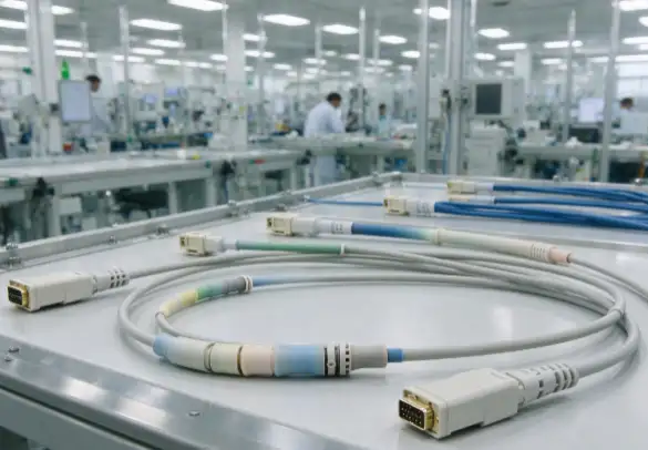
How Do Connector Interfaces and Pin Assignments Affect Compatibility?
Connector configuration is one of the first details to verify when evaluating a replacement or customized monitoring cable.
Important specifications include:
-
Connector manufacturer and part number.
-
Contact count and pin numbering.
-
Male or female interface.
-
Connector keying and orientation.
-
Straight or angled cable exit.
-
Mating-face view and wiring assignment.
-
Cable length and branch configuration.
Pin mapping deserves particular attention. Different monitor platforms may use different electrical arrangements even when their connectors appear similar.
For multi-lead ECG assemblies, verify the relationship between each leadwire, electrode connection, and monitor input. Color coding and labeling should follow the device manufacturer's approved configuration.
A controlled wiring diagram helps prevent incorrect connections during manufacturing and equipment integration. Any proposed connector substitution should be reviewed against the original interface and electrical requirements.
Signal Integrity and Patient-Side Material Considerations
Patient monitoring signals can be relatively low-level and sensitive to interference, poor contact conditions, and cable movement.
The required shielding and conductor arrangement depend on the monitoring system. Shield termination should follow the equipment manufacturer's electrical design rather than being changed independently.
Other factors affecting signal reliability include:
-
Conductor resistance and connection quality.
-
Contact stability at connector interfaces.
-
Cable movement and mechanical stress.
-
Shield continuity where specified.
-
Appropriate routing around interference sources.
Patient-side materials require a separate assessment. If a cable or accessory contacts the patient, its material selection should reflect the nature and duration of contact.
ISO 10993-1 provides a framework for biological evaluation within a risk management process. It should not be interpreted as a blanket certification requirement for every cable component.
The finished device configuration, contact classification, and applicable regulatory requirements determine the appropriate evaluation.

Cleaning and Repeated Handling: What Should Be Considered?
Reusable monitoring cables are frequently connected, disconnected, wiped, and repositioned. These activities can gradually affect the cable jacket, connector housing, overmold, and leadwire branches.
Material compatibility should be evaluated against the actual cleaning agents and procedures specified for the equipment.
Consider the following areas:
| Component |
Potential concern |
Design consideration |
| Cable jacket |
Chemical exposure and surface degradation |
Verify cleaning-agent compatibility |
| Connector housing |
Repeated mating and handling wear |
Confirm mechanical durability |
| Overmold |
Cracking or interface deterioration |
Evaluate flex and material compatibility |
| Leadwire branches |
Repeated bending and pulling |
Provide suitable strain relief |
| Labels and markings |
Fading or detachment |
Use identification methods suitable for cleaning conditions |
Repeated handling can create stress near connector exits and branch junctions. Flexible transitions and suitable strain relief can help reduce localized mechanical stress.
Reusable and single-use configurations should also be distinguished. Their material requirements, cleaning processes, packaging, and verification plans may differ considerably.
What Quality Checks Support Reliable Patient Monitoring Cables?
Verification should reflect the cable's function and intended use rather than applying an identical test package to every configuration.
Typical checks may include:
| Verification method |
Purpose |
| Continuity and pin mapping |
Confirm correct electrical connections |
| Short-circuit testing |
Detect unintended electrical connections |
| Contact inspection |
Check connector condition and termination quality |
| Pull testing |
Evaluate connection retention |
| Flex testing |
Assess resistance to repeated bending |
| Visual inspection |
Identify jacket, molding, and assembly defects |
| Cleaning compatibility assessment |
Evaluate material performance under specified cleaning conditions |
The device manufacturer's risk analysis should determine which tests are required, their acceptance limits, and whether testing applies to every assembly or representative samples.
Documentation also matters. Revision-controlled drawings, bills of materials, approved component lists, inspection records, and change histories help maintain consistency between prototype approval and subsequent production.
For additional technical detail, see SOAR's guide to medical cable assembly testing and quality requirements.
What Should Be Specified When Sourcing Patient Monitoring Cables?
A clear technical specification helps avoid connector mismatches and unnecessary design revisions.
A typical project specification should include:
-
Monitor manufacturer, model, and intended application.
-
Connector part numbers, drawings, and mating interface.
-
Pinout, lead count, and wire identification.
-
Cable length, branch dimensions, and exit orientation.
-
Patient-contact status and intended use.
-
Reusable or single-use configuration.
-
Cleaning and disinfection requirements.
-
Required inspection records and verification criteria.
If the original cable is available, its drawings and part numbers can help establish the interface requirements. However, physical similarity alone should not be treated as proof of compatibility.
Prototype samples should be evaluated using the intended monitor or an approved test setup before design release.
SOAR Medical Cable Assembly Options
SOAR's Medical Cables collection provides an overview of its medical cable product category.
The collection can serve as a starting point when reviewing cable assemblies for medical equipment. However, the public category listing does not establish compatibility with a specific patient monitor, ECG platform, or SpO2 sensor.
For customized applications, connector interfaces, conductor arrangements, cable dimensions, patient-contact requirements, and inspection criteria should be confirmed against the approved equipment specifications.
FAQ
Can a patient monitoring cable be selected by connector shape alone?
No. Connector appearance does not confirm pin assignment, electrical compatibility, lead configuration, or suitability for a particular monitoring platform.
What is the difference between ECG and SpO2 cable assemblies?
ECG cables connect electrode leads to monitoring inputs, often using multi-branch configurations. SpO2 cables connect compatible sensors to monitoring equipment and follow their specific interface and signal requirements.
Do all patient monitoring cables require shielding?
Not necessarily. Shielding requirements depend on the signal characteristics, equipment architecture, and electromagnetic environment. Follow the approved device design.
Can reusable patient monitoring cables be cleaned with any hospital disinfectant?
No. Cleaning agents and procedures should be compatible with the cable jacket, connector housing, overmold, and markings. Follow the validated equipment cleaning instructions.
What information is needed to customize a patient monitoring cable?
Provide the monitor model, connector drawings, pinout, lead configuration, cable dimensions, intended patient contact, cleaning conditions, and required verification criteria.
Reference Sources
-
U.S. Food and Drug Administration (FDA) – Quality and Compliance: Medical Devices.
-
International Electrotechnical Commission (IEC) – IEC 60601-1: Medical Electrical Equipment – General Requirements for Basic Safety and Essential Performance.
-
International Organization for Standardization (ISO) – ISO 10993-1: Biological Evaluation of Medical Devices.